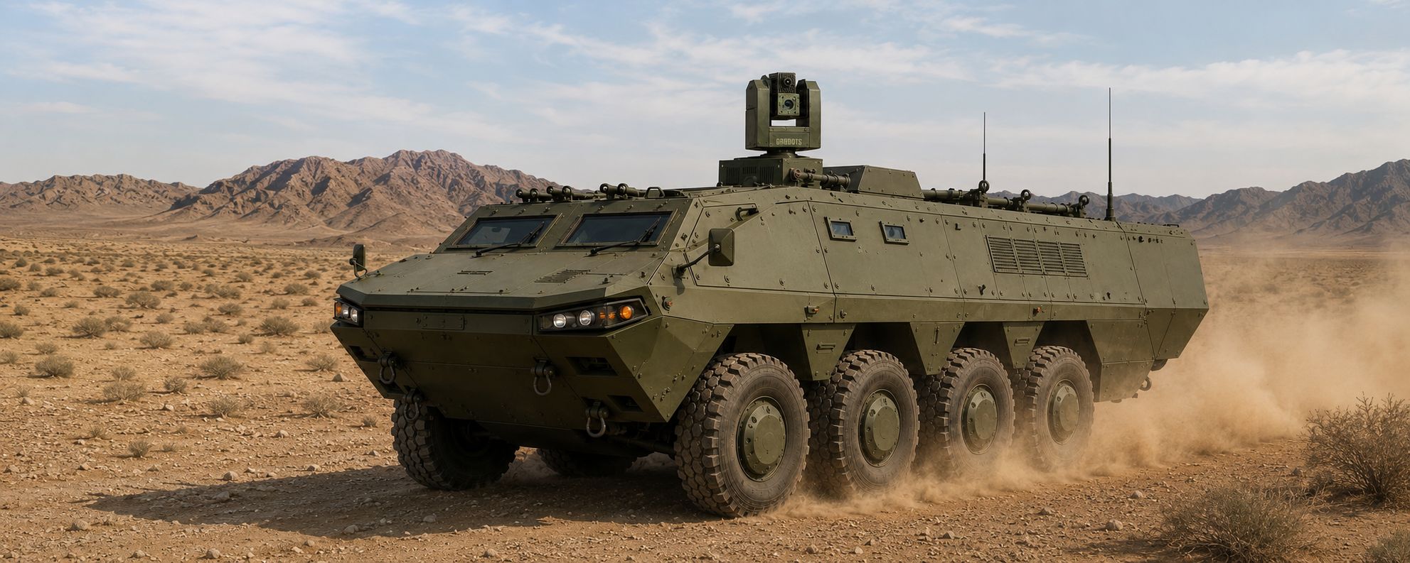
Gridbots Falcon gyro stabilised optical platform - stabilised gimbal for EO/IR payloads


Gyro Stabilised Optical Platform

Gridbots Falcon

Gyro Stabilised Gimbal for 1 kg to 10 kg Optical Payloads


Gridbots Falcon is a precision gyro stabilised optical platform that holds a mounted sensor on target while the host vehicle pitches, rolls, vibrates and turns. Inertial rate sensing, direct-drive torque motors and a closed-loop servo running at high bandwidth cancel base motion before it ever reaches the optical line of sight.

The Falcon family spans four frame sizes. The compact F1 holds line of sight to 50 µrad RMS with payloads up to 1 kg; the heavy-lift F10 carries up to 10 kg of sensor mass and holds 150 µrad RMS. Every model shares the same servo core, command protocol and mechanical interface, so a payload developed on one frame moves to another without software change.

Falcon accepts any combination of day camera, cooled or uncooled thermal imager, laser range finder, laser designator, spotter scope or SWIR module inside its payload envelope. It ships as an open stabilised gimbal for integrators, or pre-populated with a Gridbots sensor suite for turnkey surveillance, naval observation, airborne survey and vehicle-mounted sighting roles.
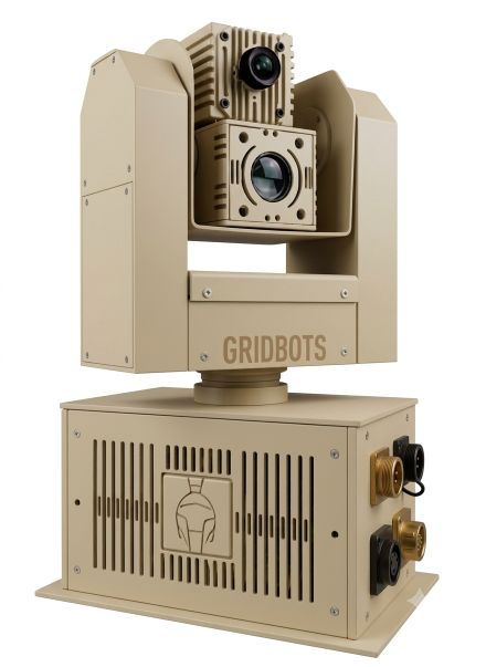


Gridbots Falcon stabilised gimbal - gyro stabilised optical platform pod

Gyro Stabilised Optical Platform


50 µRAD
Best Stabilisation Accuracy
1 - 10 KG
Payload Capacity
4-AXIS
Coarse + Fine Stabilisation
360°
Continuous Azimuth

50 to 150 µrad RMS

Line-of-Sight Stabilisation

FOG + MEMS Inertial Sensing

Rate Feedback

1 kg to 10 kg Payload

Four Frame Sizes

Land · Naval · Airborne

Common Servo Core


The Falcon Model Range

Four frames, one servo architecture. Stabilisation accuracy trades against carried mass: the lighter the payload and the smaller the inertia, the tighter the loop holds. Pick the frame by payload mass first, then confirm the stabilisation figure meets the mission's angular budget.


FALCON F1
Compact
50 µrad
RMS line of sight
  • Up to 1 kg payload
  • FOG rate gyro
  • 120°/s slew
  • UAV, mast, tripod
FALCON F3
Mid-Frame
75 µrad
RMS line of sight
  • Up to 3 kg payload
  • FOG rate gyro
  • 90°/s slew
  • Light vehicle, USV
FALCON F5
Long Range
110 µrad
RMS line of sight
  • Up to 5 kg payload
  • MEMS + FOG hybrid
  • 60°/s slew
  • Naval mast, border post
FALCON F10
Heavy Lift
150 µrad
RMS line of sight
  • Up to 10 kg payload
  • MEMS + FOG hybrid
  • 40°/s slew
  • Vehicle sight, coastal


ParameterFalcon F1Falcon F3Falcon F5Falcon F10
Maximum Payload1 kg3 kg5 kg10 kg
Stabilisation (RMS)50 µrad75 µrad110 µrad150 µrad
Stabilisation Axes4 (2 coarse + 2 fine)4 (2 coarse + 2 fine)4 (2 coarse + 2 fine)4 (2 coarse + 2 fine)
Inertial SensingFibre-optic gyroFibre-optic gyroFOG + MEMS hybridFOG + MEMS hybrid
Servo Bandwidth90 Hz70 Hz50 Hz35 Hz
Maximum Slew Rate120°/s90°/s60°/s40°/s
Angular Acceleration250°/s²180°/s²120°/s²80°/s²
Pointing Repeatability0.2 mrad0.3 mrad0.4 mrad0.5 mrad
Azimuth TravelContinuous 360°Continuous 360°Continuous 360°Continuous 360°
Elevation Travel−60° to +90°−60° to +90°−45° to +85°−40° to +80°
Platform Mass (unloaded)3.5 kg7.5 kg13 kg24 kg
Power (nominal / peak)45 / 90 W70 / 140 W110 / 220 W180 / 360 W
Ingress ProtectionIP66IP66IP67IP67

Stabilisation figures are RMS residual line-of-sight error measured at maximum rated payload on a 6-DOF motion table under the reference sea-state / cross-country profile. Lighter payloads improve the figure.


Features of the Falcon Stabilised Platform


Four-axis stabilisation - coarse gimbal plus fine steering stage

50 µrad RMS line of sight on the F1 frame

Payload capacity from 1 kg to 10 kg across four frames

Direct-drive brushless torque motors - no backlash, no gear train

Continuous 360° azimuth on slip ring

Open payload bay - any EO, IR, SWIR, LRF or designator combination

Common command protocol across the whole model range

Geo-pointing, slew-to-cue and scan patterns built in

Auto payload balancing and inertia auto-tune on power-up

Sealed to IP66 / IP67 with dry-nitrogen purge port


Stabilisation Performance

Residual line-of-sight error is what decides whether a long-focal-length sensor produces a usable image from a moving platform. At 50 µrad, the Falcon F1 holds a target inside a single detector pixel of a 90× zoom camera at 2 km. The tables and charts below show measured residual error against base-motion severity and payload mass.


Base Motion ConditionF1 (1 kg)F3 (3 kg)F5 (5 kg)F10 (10 kg)
Static tripod / fixed mast18 µrad26 µrad38 µrad52 µrad
Metalled road, 40 km/h30 µrad44 µrad62 µrad85 µrad
Cross-country, 20 km/h50 µrad75 µrad110 µrad150 µrad
Sea State 3 (naval mast)42 µrad64 µrad95 µrad132 µrad
Sea State 5 (naval mast)65 µrad98 µrad140 µrad195 µrad
Rotary-wing airframe vibration55 µrad82 µrad125 µrad

Values are RMS residual line-of-sight error at maximum rated payload for each frame. Quoted headline accuracy corresponds to the cross-country reference profile.


Stabilisation Accuracy by Model (µrad RMS)
Payload Capacity by Model (kg)

Residual Line-of-Sight Error vs Base Disturbance — Stabilised vs Unstabilised

Logarithmic scale. An unstabilised hard mount passes base motion straight to the optical axis; the Falcon servo rejects it by two to three orders of magnitude.


Payload Mass vs Achievable Stabilisation
Capability Profile Across the Range


Payload Integration

The payload bay is an open mechanical volume with a bolt pattern, power rails and data lanes brought through the slip ring. Mount a sensor, declare its mass and centre of gravity, and the platform runs an inertia auto-tune on the next power-up. No servo re-tuning by hand, and no controller firmware change when moving a payload between frames.


Payload BayF1F3F5F10
Rated Mass1 kg3 kg5 kg10 kg
Usable Volume (L×W×H)180×140×120 mm260×190×170 mm340×240×220 mm460×320×290 mm
CG Offset Tolerance±8 mm±12 mm±18 mm±25 mm
Payload Power Available40 W80 W150 W300 W
Data Lanes Through Slip Ring2× GigE, 1× RS-4222× GigE, 2× RS-4224× GigE, 2× RS-4224× GigE + CoaXPress, 4× RS-422


Typical PayloadMassRecommended Frame
HD day camera, 30× zoom0.6 - 0.9 kgFalcon F1
Uncooled LWIR imager (640×480)0.4 - 0.8 kgFalcon F1
Day camera + uncooled thermal + LRF2.2 - 2.8 kgFalcon F3
Cooled MWIR imager with continuous zoom3.5 - 4.5 kgFalcon F5
Long-range EO/IR suite + eye-safe LRF + SWIR4.5 - 5.0 kgFalcon F5
Multi-sensor suite with large-aperture telescope7 - 10 kgFalcon F10
Survey / mapping camera with IMU-INS block6 - 9 kgFalcon F10


Specifications


Model NumberGB-FALCON (F1 / F3 / F5 / F10)
TypeGyro Stabilised Optical Platform / 4-Axis Stabilised Gimbal
Line-of-Sight Stabilisation50 µrad RMS (F1) to 150 µrad RMS (F10)
Payload Capacity1 kg (F1), 3 kg (F3), 5 kg (F5), 10 kg (F10)
Stabilisation ArchitectureTwo-axis coarse gimbal with two-axis fine steering stage
Inertial SensingFibre-optic rate gyro; FOG + MEMS hybrid on F5 / F10
DriveDirect-drive brushless torque motors, gearless
Angle FeedbackAbsolute optical encoder, 22-bit
Azimuth TravelContinuous 360° (slip ring)
Elevation Travel−60° to +90° (frame dependent)
Slew Rate40°/s to 120°/s (frame dependent)
Pointing Repeatability0.2 mrad to 0.5 mrad
ModesStabilised stare / Manual / Geo-point / Scan / Slew-to-cue / Track follow
NavigationDifferential GPS, dual-channel compass, 10-DOF low-drift IMU
InterfaceGigabit Ethernet, RS-422, CoaXPress (F10), discrete I/O
Control ProtocolGridbots open gimbal protocol; common across all frames
Input Power18 - 32 VDC; 45 W to 180 W nominal by frame
Ingress ProtectionIP66 (F1 / F3), IP67 (F5 / F10)
Operating Temperature−30 °C to +60 °C
EnvironmentalDesigned to MIL-STD-810; EMI/EMC to MIL-STD-461
MountingVehicle roof, telescopic mast, naval deck pedestal, airborne nose ball
Gridbots Falcon gyro stabilised optical platform - gimbal axes and sensor icon


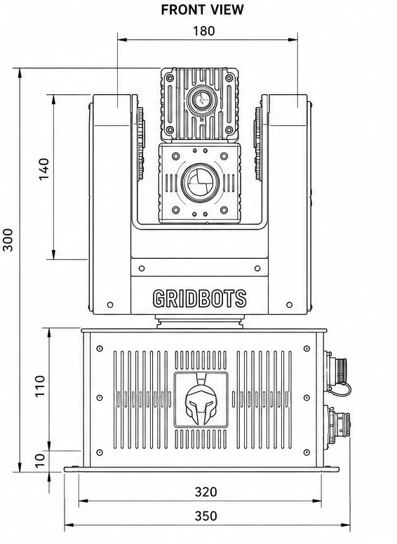
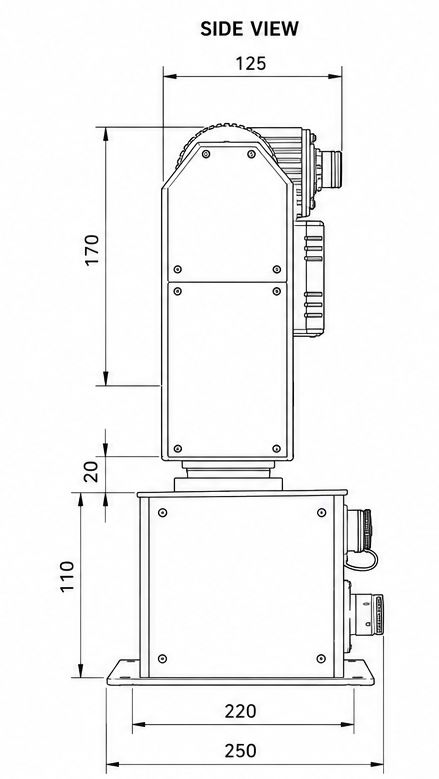
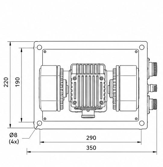
Drawings

Gridbots Falcon gyro stabilised optical platform drawing - front view
Gridbots Falcon stabilised gimbal drawing - side view


Gridbots Falcon stabilised optical platform drawing - top view
Gridbots Falcon gimbal drawing - payload bay dimensions


Falcon: Gyro Stabilised Optical Platform & Stabilised Gimbal

The Gridbots Falcon is a four-axis gyro stabilised optical platform built for sensors that have to stay on target from a moving host. As a stabilised gimbal it uses direct-drive torque motors, absolute encoders and fibre-optic rate gyros to reject base motion, delivering line-of-sight stabilisation from 50 µrad RMS on the compact F1 frame through to 150 µrad RMS on the heavy-lift F10. Payload capacity spans 1 kg to 10 kg, so the same platform family covers a single lightweight day camera on a UAV, a fused EO/IR and laser range finder suite on a vehicle mast, and a large-aperture long-range telescope on a coastal or naval pedestal. Continuous 360° azimuth, geo-pointing, slew-to-cue and a shared control protocol across every frame make the Falcon a straightforward stabilised camera platform for integrators building surveillance, observation, survey and sighting systems.